[★★★☆☆] Reinforced Concrete Section Analysis
In this page, the analysis of a rectangular reinforced concrete section of a 2D beam is performed to compute the full
plastic moment. This is achieved by using the SingleSection2D
element. There is no need to create a larger model.
The model can be downloaded. rc-section-analysis.supan
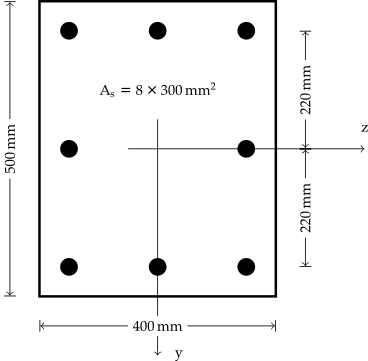
Section Definition
The section configuration is shown as follows.
Model Development
The SingleSection2D element is NOT a connector element.
Only one node is required to define the element.
First, we define an arbitrary node.
| Text Only | |
|---|---|
For material models, we use a simple concrete model that adopts Tsai's
backbone ConcreteTsai and
the MPF steel model.
With the above definition, we have \(f_c=30~\text{MPa}\), \(f_t=3~\text{MPa}\), \(\varepsilon_c=0.002\), \(\varepsilon_t=0.0001\), \(E=200~\text{GPa}\) and \(f_y=400~\text{MPa}\). For detailed material definitions, please refer to the corresponding pages.
Now we define a rectangular concrete section with the dimension of \(400~\text{mm}\times500~\text{mm}\) and nine integration points along section height. Since it is a 2D section, it is meaningless to define multiple integration points along \(z\) axis. All 2D sections only use 1D integration schemes along \(y\) axis.
| Text Only | |
|---|---|
Now define some rebars. The eccentricities are \(\pm220~\text{mm}\) and \(0~\text{mm}\).
To combine those independent sections into a whole, we use
the Fibre2D section. It is a wrapper that wraps all valid sections
into one piece. Accordingly, a SingleSection2D element can be
defined.
Before defining steps, we first create two recorders to record nodal reactions and displacements.
If the axial deformation shall be suppressed, the first DoF needs to be restrained. Here, instead of doing that, we apply an axial force of \(10\%\) section capacity, which is \(600~\text{kN}\).
| Text Only | |
|---|---|
Now in the second step, a rotation of \(10^{-4}\) is applied on the second DoF.
| Text Only | |
|---|---|
Result
Perform the analysis, the rotation versus moment can be plotted. The maximum moment under such a loading configuration is about \(350~\text{kNm}\).

Users with a relative background may help to justify the result.
Asymmetric Layout
If the layout is asymmetric, say, for example, the rebars at \(y=-220~\text{mm}\) are removed.
| Text Only | |
|---|---|
In this case, a positive moment makes the unreinforced region in tension. This decreases the moment capacity. However, a negative moment does not change the moment capacity significantly.
Interested readers can try to apply both positive and negative rotation and verify the results.